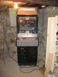
I spent a bit more time bringing the pieces of the cabinet together.
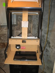
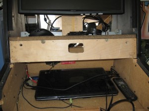
The monitor support with the flat panel mount was installed to a 3/4 inch piece of plywood, and attached to the original CRT mounting bracket.
You can also see the laptop mounted on the sliding tray, and the 12v cooling fan I installed in the back of the compartment.
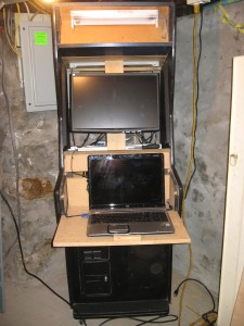
The next step was to mount the 23″ LCD screen.
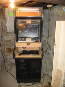
I set the machine to “Do Nothing” when the lid is closed, and set the primary monitor to be the LCD in the cabinet.
Time to test:
Cool, it works.
Next I’ll put on the main piece of the control door.
I made sure to get new bolts with wider washers to support the weight of the door when the new heavier control board is installed.
I carefully installed and bolted the control panel into the door.
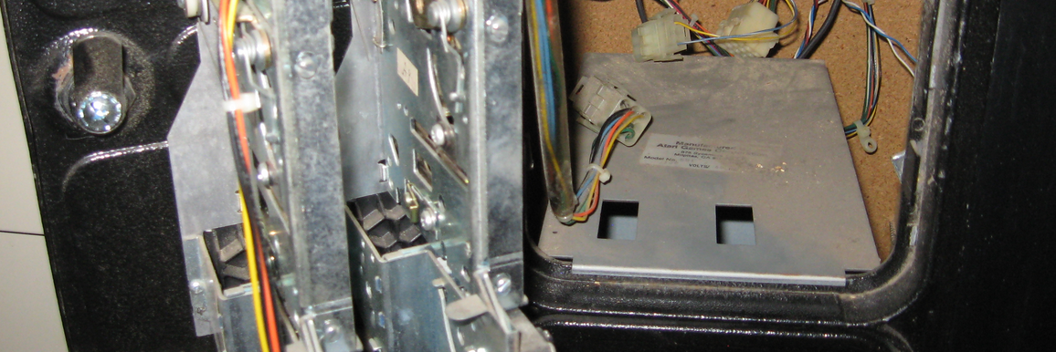
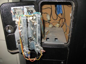
The next step was to rig up the coin door to be functional.
At the bottom of the mechanism are two small microswitches that run into the harness that folds around into the cabinet.
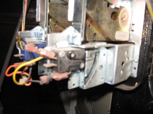
Each one grounds to the same place, but has a separate positive.
I traced them back into the plugs inside the cabinet…
I figured out which wires in the old harness were the ground and positives for each switch and spliced into them, running the left switch up to Coin 1 on the I-Pac and the right one to Coin 2, the ground wires were run to the main ground distribution block.
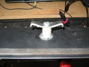
I also had to fabricate a new way to lock the control board door, the old particle board that was the latch-catch was damaged when the old lock was removed when I got the cabinet from recycling.
I fabricated a new one from plywood.
Also I had to modify the latch itself to catch on the different thickness of board.
A nice good smack from a hammer worked just right.
More updates are coming as soon as I get more pictures processed and more work done.
Thanks for visiting.
